The value added by a stamping operation, is to create distortions with a Sheet metal component commonly referred to as “Part Shape”.
The vertical press motion is transformed, by the die geometry, into horizontal and angular forces within a sheet metal blank, creating stresses within that blank. If the stress is in excess of the yield strength of the material, a permanent change in shape occurs. The stress applied-produces strain within the blank material, resulting in displacement (stretching or compression) of the original size and shape of the blank. The Die makers and die designers applied Years of accumulated knowledge and experience, to predict how a press and die would focus and/or control the amount of movement and direction of that displacement. That knowledge was utilized within computer systems to create a “Computer Aided Design” for the various stamping dies needed to not only produce the part shape but to finish the final trimmed, pierced and flange product.
Within a “CAD” design common terms are applied to help understand the metal movement and forces that interact to produce that die’s output.
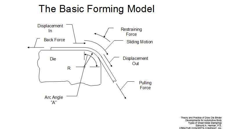
Figure 1: The basic forming model is the pulling of sheet metal off a floor in which the stretching is causing some “back force”, across a die radius and into a wall.
When creating segments of a die design, the CAD operator’s vocabulary would primarily consist of the terms: floors, walls, and radii (which may have a die or part location reference).
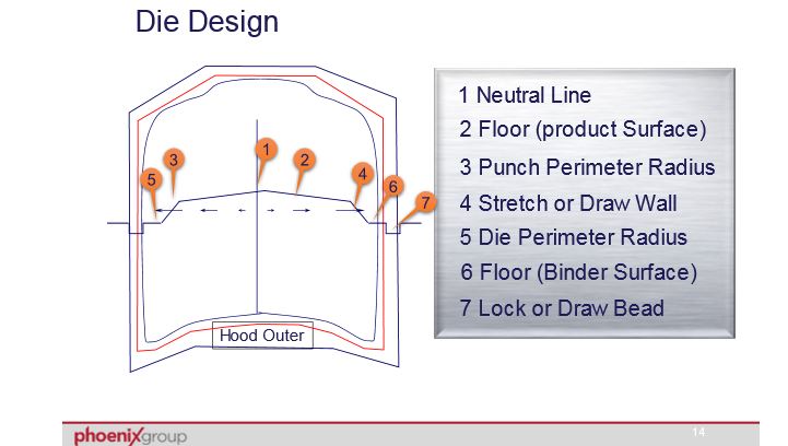
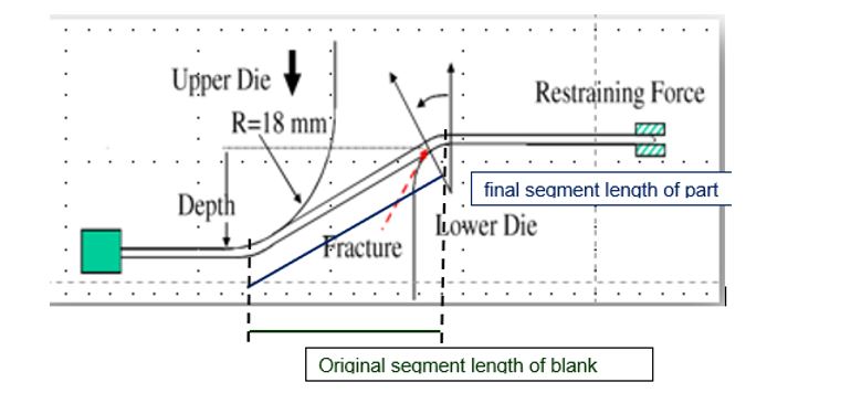
A “floor” is a line segment of the die design which is nearly horizontal (90 degrees to press motion). In a symmetrical die, where a duplicate but geometrically reversed die design acts in the opposite direction the termination of the floor is referred to as a “neutral line”.A wall is section or segment of the part shape, which is typically tipped between 15 and 90 degrees off of the horizontal. In the example below the final length (blue line) is longer than the original blank section. The difference (Final length minus original length) divided by the original length is the percentage of change. Some of the change in length will be the result of the stretching the blank material between the radii. Additional material will have been pulled into the final segment from the adjacent floors.
The blank material which is displaced from the floor into the stretch or draw wall, bends and then straightens as it passes over the adjoining segment (radius) tangent to the floor.
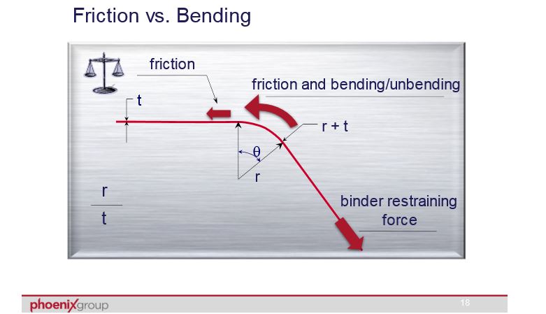
This bending and unbending produces restraining forces not only from the yield strength of the blank material, but the size of the radius. A higher strength material exerts more force against the die radius resulting in higher fictional forces within the restraining factor.Additional resistance to material sliding off the floor and into the stretch/draw wall is realized as the size of the radius is reduced. Smaller radii produce greater friction and less metal movement.
The die design will also consider the angle that the wall to the floor forms. A greater wall angle (80 degrees off the horizontal versus 60 degrees off the horizontal) will have a longer segment length around a duplicate size radius and the amount of friction that longer arc length will impart is proportional to the tangent-to-tangent segment length.With a good die design to construct the die, and a craftsmanship-built die line, the battle to create initially consistent quality parts is won, but the “production” war isn’t complete. A fully analyzed draw panel (and any redraw line die panels) should be saved for when: Die wear, material vendor change(s), press or recipe set-up changes, or an over-zealous attempt at material utilization or continuous improvement, alters strains in any of the segments of the panel. The results might be higher strains in a segment (stretch/draw wall) adjacent to a galled radius, or a low that reappears on the floor inboard of that galling due to a localized reduction in-line with the galling.